Blog - EXPERTISES & INNOVATIONS - Relais statiques - What is a back-to-back Thyristor
Solid State Relays (SSR) are switching devices made with electronic components.
The Thyristor is the power element and is the “heart” of the SSR.

All our Solid State relays are fitted with back-to-back thyristors which are also named Silicon Controlled Rectifier, SCR.
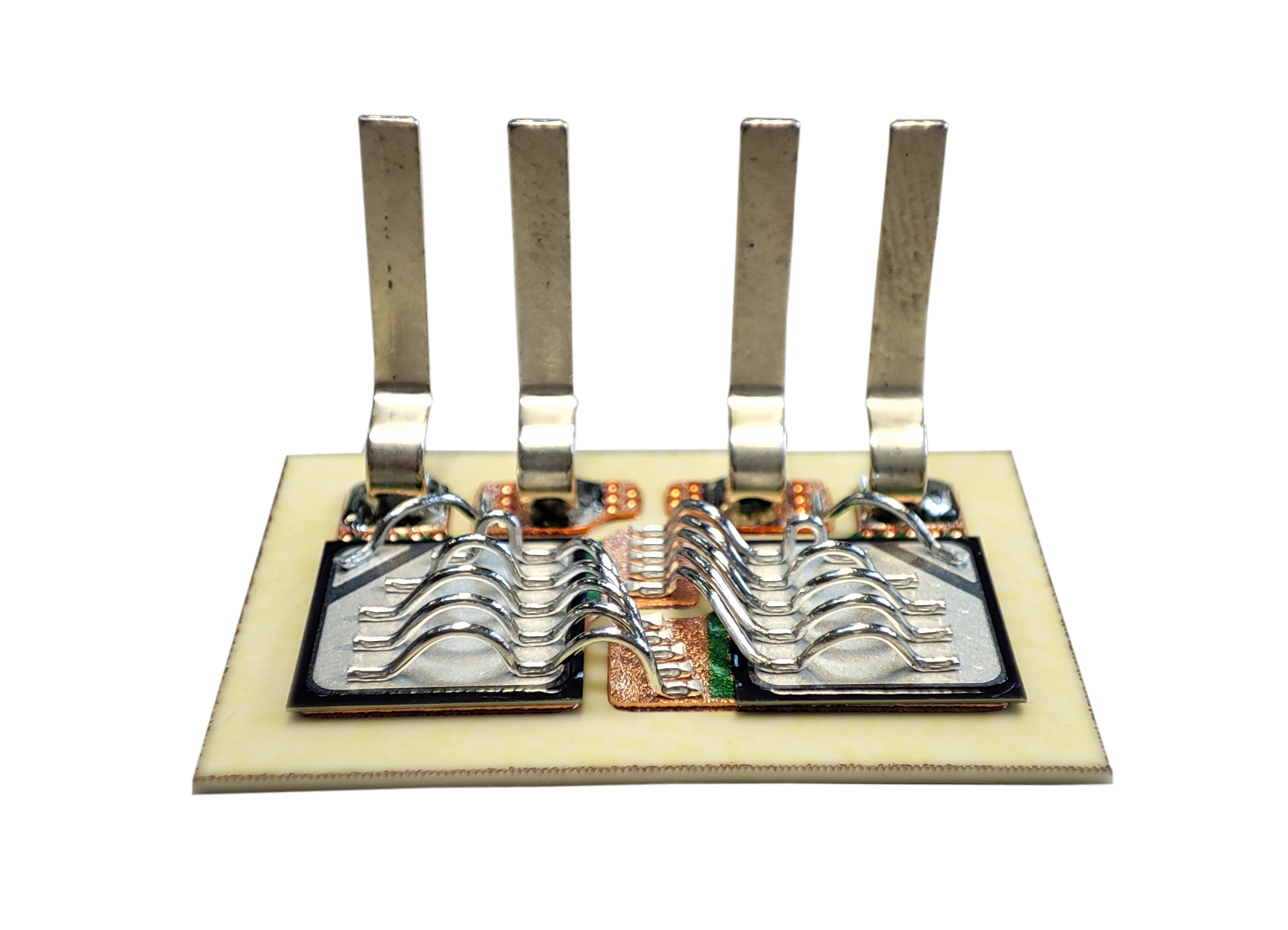
Celduc’s back-to-back thyristors are using TMS² Technology.

On the market, we can find Solid State Relays using different technologies. There are mainly 2 kinds of Technologies :
Used by the majority of the Solid State Relays manufacturers.
Conventional ceramic substrate and cathode connections, known as “jumpers”, are used. See mounting technology below :
This technology has the following disadvantages :
The innovation is in the substrate. Thanks to a high temperature (approx. 1000°C) diffusion process, a thick layer of copper (usually 0.4 mm) is directly imbedded onto the alumina substrate. The jumpers are replaced by a multitude of bonding wires with several anchor points to withstand significant overload currents. This technology brings the following advantages :
A Solid State Relay is a macrocomponent using power thyristors, optocouplers and other standard electronic components. When used well, a solid state relay has a lifespan greatly higher compared to an electromechanical relay (no moving mechanical parts subject to wear and tear or deformation).
TO REMEMBER : Lifetime expectancy of power electronic components is typically constrained by the thermal limitation (thermal stress, due to variations in temperature range during use).
Temperature variation has some effect on thyristor performances. Indeed, every switching ON/OFF during the use, brings some temperature variation on the Thyristor chip due to different factors:
–> fig 1 : temperature variation on a resistive load with significant variation during the preheating phase (ΔT1) , then less during the regulation phase (ΔT2).
–> fig 2 : temperature variation on a motor with significant variations (ΔT2) at every start-up due to starting currents which can reach 8 x In (nominal current) for 1.6s.
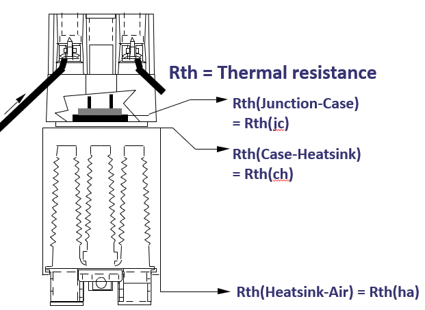
DCB technology ensures a significant reduction of this Rthj/c value.
The difference in temperature between the junction and the heatsink (case) is directly related to the thermal impedance and the power dissipation: ΔTj/c= Zthj/c x Pd. (The heatsink stays at a fairly constant temperature during normal operation).

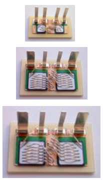
–> The bigger is the chip, the weaker is the dissipated power with : Pd = 0.9Vt x I + rt x I² t
The dynamic resistance “rt” drops with a bigger chip. The junction/case (Rthj/c) thermal resistance is also inversely proportional to the surface area of silicon (ΔTj/c= Rthj/c x Pd). This is why celduc® takes special care to properly size its Thyristor chips.

TMS² technology gives to celduc’s Solid State Relays a vey high life-time expectancy compared to the majority of products on the market. Celduc’s R&D makes regular improvement on our production process which increase constantly the number of cycles.